Web Updated;
15/05/2024
Mail me!
LC Match
|
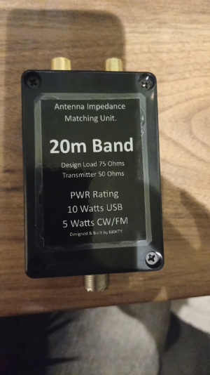
This page describes the process and build of a LC matching network to facilitate the correct integration between a typical Dipole Aerial and a 50 Ohm feedline, normally Coax. The Dipole in its "Flat" leg configuration generally
presents between 70 and 75 Ohms impedance at the feed point. Bending the two
ends of the dipole elements downwards towards 45 degrees often decreases the
impedance to around 50 Ohms but compromises take off angles. Generally most
dipoles are fed using Coax, I accept that you can feed a dipole with ladder line
(or window line as it is sometimes referred) but the ladder lines are generally manufactured
in either 300 Ohm or 450 Ohm and also provide a feed point mismatch, I would
argue that a "dipole" fed with ladder or twin feeder line is a doublet
and not a dipole but that is a topic for another page! So, generally if a Dipole is being constructed and fed through
a length of Coax rated at 50 Ohms the maximum Vswr that can be obtained is
1:1.5, Because 75 Ohms divided by 50 Ohms = 1.5. One way is to create a LC circuit to either load the antenna with inductance or add capacitance to match the impedance to 50 Ohms. This is done with a circuit called an LC circuit. The configuration can be Hi-Z to Lo-Z or configured Lo-Z to Hi-Z, in fact if the circuit is constructed in such a way that provides identical connections as required to each side, the same circuit can be used in reverse to achieve the alternative effect. See diagram below courtesy of Ham Radio Secrets. (www.hamradiosecrets.com)
|
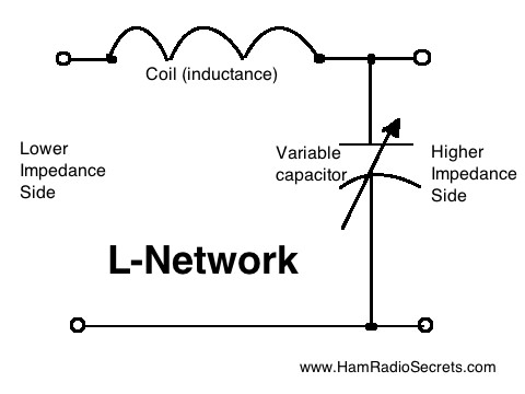 |
The circuit diagram on the left (page link above) shows
a basic LC circuit (LC-Circuit
Wikipedia) with a coil (Inductor) and Variable Capacitor. There are a number of purposes for using the LC circuit but here we are concerned with impedance matching in an AC circuit. Here, referring to the diagram (left) our example shows the Radio and coax (50 Ohms) on the lower impedance side and the antenna (75 Ohms) being on the higher impedance side. The setting of the variable capacitor (VC) changes the impedance match and reduces the higher Impedance to match the 50 ohms. Calculators are available for use on the internet but generally for 75 Ohm to 50 Ohm I have used values around 105 pF and 390-400 nH. Generally, I make up a non inductive load in resistors to the value of 75 Ohms and place this in parallel across the Load point in the circuit. Shown left as the two circles at the top right and bottom right of the diagram. Then place an air wound inductor (I use enamelled copper wire) in series from the centre wire of the coax to one of the dipole connection points. Using a VNA or antenna analyser ( I have a RIGEXPERT AA55 Zoom but for this I used the MFJ 259B) measure the Ohms impedance and tune in the best result using the VC. Some minor tuning may be required when erecting the circuit with the aerial as the 75 Ohm resister load cannot reproduce the complexities of an aerial in its free space in a world environment but it will get you to a close starting point. |
|
|
|
|
|
|
|
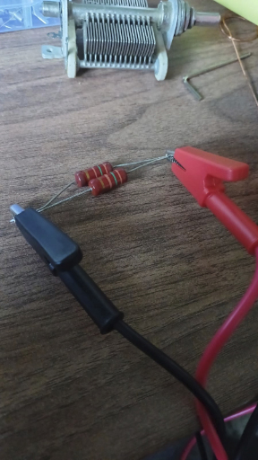
Selecting a pair of 150 Ohm
resistors. |
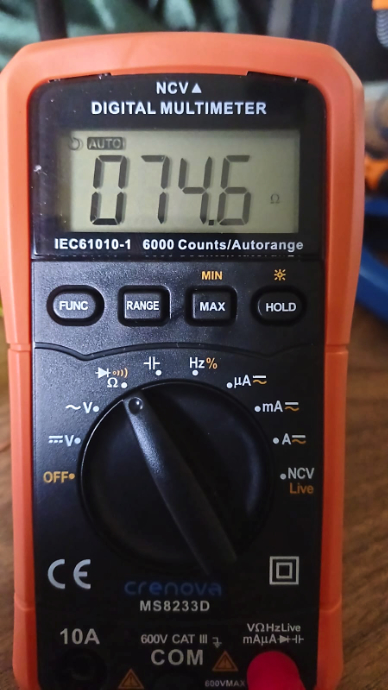
Here was the Impedance measure |
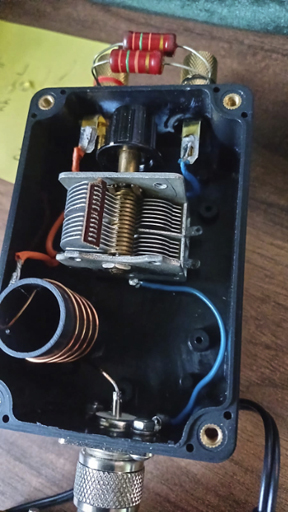
Here you can see the construction, |
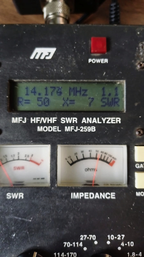
This is the reading from the MFJ259B |
A simple way to finish the box is by |
|
A couple of additional notes specific to the variable capacitor, Before you install the VC use a continuity check on a multi-meter and whilst slowly rotating the spindle (rotor) on the capacitor place one probe of the meter on the chassis of the capacitor and the other probe on the stator connection. The meter should not show "0" or bleep, move the spindle on the capacitor slowly from one side to its full extent and check that the meter shows no short contact. (closed circuit) This is very important because you must not have any of the plates touching making a DC short between the two parts of the capacitor. If you do get an indication of a short the capacitor needs careful visual checking to examine where the two plates are touching. If they cannot be corrected by very gentle bending then the capacitor can not be used. Also, when wiring up the capacitor it is important that the spindle and chassis of the capacitor is wired to the Ground side of the SO239, this is especially important when using a metal chassis or box to house the project in or where (in a different aspect) the rotary spindle protrudes the chassis and could be touched by the operator during TX transmit. If you have a VNA or antenna analyser like the MFJ you should be able to see the changes when you rotate the spindle. I didn't need to place a knob on the end of the spindle but it did make alteration much easier. The capacitor had a range of 10 to 300 pF and you can see that it is nicely configured mid range which gives plenty of adjustment +/- |
Actual testing and configuration in the real world!
| The antenna was erected using a dipole cut for
20m band with a centre freq of 14.175 MHz. There was a minor adjustment required
to increase the amount of capacitance by 5mm as measured at the outside of the
rotor shown by the brown insulation material. The match worked great and
measurements taken on site with my AA55 Zoom showed a good return loss X=5 and
Rs=49.7 Ohms and a Vswr of 1:1.2 The antenna was built for a QRP Chinese radio which outputs 5 watts max, so the capacitor did not have to have very wide plate spacing. Consideration on the air gap spacing between the capacitor plates should be made before designing and constructing this type of circuit for higher power Radios. |

